DIY Analogue RCA Interconnects Recipe
An RCA connector, sometimes called a phono connector or cinch connector, is a type of electrical connector commonly used to carry audio and video signals. The connectors are also sometimes casually referred to as A/V jacks. The name “RCA” derives from the Radio Corporation of America, which introduced the design by the early 1940s for internal connection of the pickup to the chassis in home radio-phonograph consoles. It was originally a low-cost, simple design, intended only for mating and disconnection when servicing the console. Refinement came with later designs, although they remained compatible.

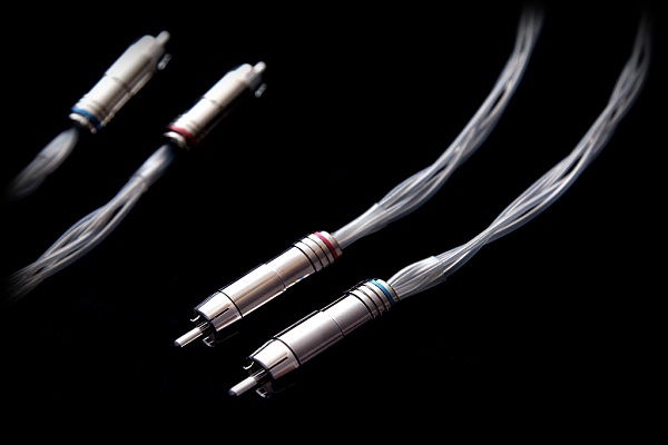
Analogue unbalanced interconnects, also known as Analogue RCA interconnects or cables, are used for connecting line level equipment such as CD player or DAC to a pre-amp or amplifier. If you want to install custom audio systems in your home, DIY (Do-It-Yourself) RCA cables ensures that you have a clean system with no excess cable. Here’s an easy DIY analogue RCA interconnects recipe:
Materials
- Set of 04 RCA plugs as this recipe is for a stereo connection – Left (L) and Right (R)
- Two sets of multi-conductor cables of equal length
- Wire cutter
- Wire stripper
- Helping hands with alligator clips or tweezers
- Table-top or suction base vise
- Solder
- Soldering iron with a minimum of 25 watts and a narrow conical tip
- Linesman pliers
- Heat shrink in 02 different colors and sizes (optional)
- Heat gun (optional)
- Cable tester or a digital multimeter

Method
Turn on the soldering iron.
- Do this first so it is hot enough when you begin soldering.
- Make sure the tip of the iron is placed inside the soldering iron stand, and that it is safely out of the way so you do not accidentally bump into it.
Cut the audio cables to the length that you need. For this recipe we will consider the cables as having 04 individually insulated conductors – 02 for hot and 02 for cold pins.
- Choose a length that is appropriate for the application. Recommended length is ideally between 0.5m to 10m.
Remove or strip 1/8 inch (4 mm) of the individual jacket around the conductor wires.
- If the cable is too big to fit in one of the gauge holes on a wire cutter, use the sharp edge at the base of the wire cutters.
- Apply light pressure with the cutting tool and spin the cable around until you cut all the way through the outer jacket. Be careful to avoid cutting the conductor wires.
- Cables may have between 2 to 16 conductors. If there is just 02 conductors, just twist the cable together. If the conductors are in multiples of 03 then braiding the common colors together is another effective way of managing the cables.
- Coat or tin the conductor ends. Applying a small amount of solder to the twisted ends keeps them together and it will be easier to connect them to the RCA end.
- Heat up the wire and hold the solder on the opposite side of the iron touching the wire. The heated conductor wire should be hot enough for the solder to melt and apply an even coat on the exposed conductor tips.
Use heat shrink (optional).
- Cut a small diameter heat shrink tube about 1 inch (2.5 cm) long. Slide the heat shrink over the conductor wires onto the cable itself.
Disassemble your RCA plugs and keep all components neatly in one place.
- Being organized and methodical goes a long way in DIY cable making.
Slide the outer barrel of the RCA end onto the cable past the conductor wires.
- This is necessary in order to be able to screw the barrel back once you’ve soldered the conductors to the RCA plugs.
Solder the conductors to the RCA plug.
- Place the RCA plug’s sleeve in-between the jaws of the table-top vise and lock it in place.
- Align the stripped cable in line with the RCA plug’s arm using the helping hand as shown in the picture below.
- If the individual conductor’s insulation is not color coded then use a removable tape to mark the individual cables, on either end, for easy identification. Remove the tapes once the cables are soldered to their respective pins.
- Find the U-shaped solder cup that runs in line with the center pin’s tip (signal) as shown in the picture above. Insert the tinned signal conductor end into the solder cup and apply the soldering iron to the tip of the exposed conductor.
- Find the long tab / arm (return) that extends out of the RCA’s sleeve and has a hole in the center. Insert the tinned ground conductor end into the hole and apply the soldering iron to the tip of the exposed conductor.
- Apply just enough solder that can hold the conductors to their respective pins – no less, no more!

Press the cable clamp with a linesman pliers.
- This ensures that the hot and cold conductors are held firmly in place.
- Pull the heat shrink over the cable clamp and shrink it with a heat gun. This process adds rigidity and flexibility to the cable.
Thread the outer barrel and the RCA plug’s head (sleeve) together.
Repeat the above steps for the remaining 03 RCA plugs.
Test the cables for continuity and correct polarity using a cable tester or a digital multimeter.
Apply medium diameter heat shrink, specifically designed for RCA plugs, partially over the RCA barrel and the cable using a heat gun for added appearance and rigidity (optional).
- If you plan on making multiple RCA cables for 5.1 or 7.1 application then use different colored heat shrinks for easy identification.
Tips
If possible, use a high-quality soldering iron. A good soldering iron heats up to a higher temperature than the lower-quality models. The process will be easier and the results will be much cleaner.
The location of an RCA plug’s ground connection (arm) and the shape of the solder cup will vary from design to design.
Some RCA plugs do not have a cable clamp on the ground connection (arm), instead there could be a separate chuck just like the ones found inside XLR plugs. These chucks are used to hold or lock the positive and negative conductors firmly in place, inside the RCA plug. Applying a heat shrink on top of the chuck ensures an even more robust and flexible connection. The Eichmann bullet plugs, are an exception, they neither have a cable clamp nor a chuck; it comes with a hollow rubber bushing and two tiny screws on either side of the barrel – to squeeze the bushing that helps hold most cables firmly. Use of heat shrink is indispensable in this design.

Controversies
There are some controversies that every DIY audiophile and cable manufacturer is bound to face it at some point or the other. They make for some really interesting read. Here are the most popular ones:
Dielectric material: The type of dielectric material used affects the quality of sound. The lower the dielectric constant the better the sound quality.
Heat shrink: When used to add rigidity to the cable clamp could affect the quality of sound due to the change in the dielectric constant.
RCA plugs: Available in brass, copper and silver that are plated with noble metals to avoid corrosion. There is a school of thought that believes that the material used does not matter as long as the RCA plugs are well designed and made.
Conductors: Available as solid core or stranded ranging from 30 AWG (American Wire Gauge) to 22 AWG in 02 to 16 conductor / strand designs for making analogue interconnects. They are also available in copper and silver in various purity ratings. Copper is claimed to have a warm sound, whereas, silver is claimed to have a well-lit presentation. There is a school of thought that believes that a cable of sufficient gauge, regardless of the type of metal used, should not make any audible difference at all.
Shielding: A tubular copper or aluminium braid / foil which covers the entire length of the cable bundle is the standard. It’s suggested that most A/V playback systems may not need shielded RCA cables if the lengths are kept reasonably short. In some environment, unshielded RCA cables may introduce audible hum due to EMI (Electromagnetic Interference) / RFI (Radio-Frequency Interference) from adjacent electronic equipment or mobile phones.
Braiding: When 03 or more conductors are used braiding helps in cable management and appearance. Some claim that braiding also acts as a shield against EMI / RFI.

Wrap-up
Every cable design is subject to some kind of a compromise; it’s a balance between performance and penalties. This DIY analogue RCA interconnects recipe is just one way to skin a cat. This post is likely to be updated time and again with either relevant points or photographs.
Experienced DIY enthusiasts may have an advantage due to their thorough understanding of metallurgy, quality of materials used, cable geometry and of course craftsmanship that comes only with practice. If you have limited soldering experience, ask a DIY specialist to do the job for you.
DIY opens up to a world of endless possibilities for every audiophile. Apart from understanding and eliminating bottle-necks that improves A/V playback performance, it is also a very creative process.
If you want us to build this cable for you then kindly contact us and we are more than happy to assist you.